
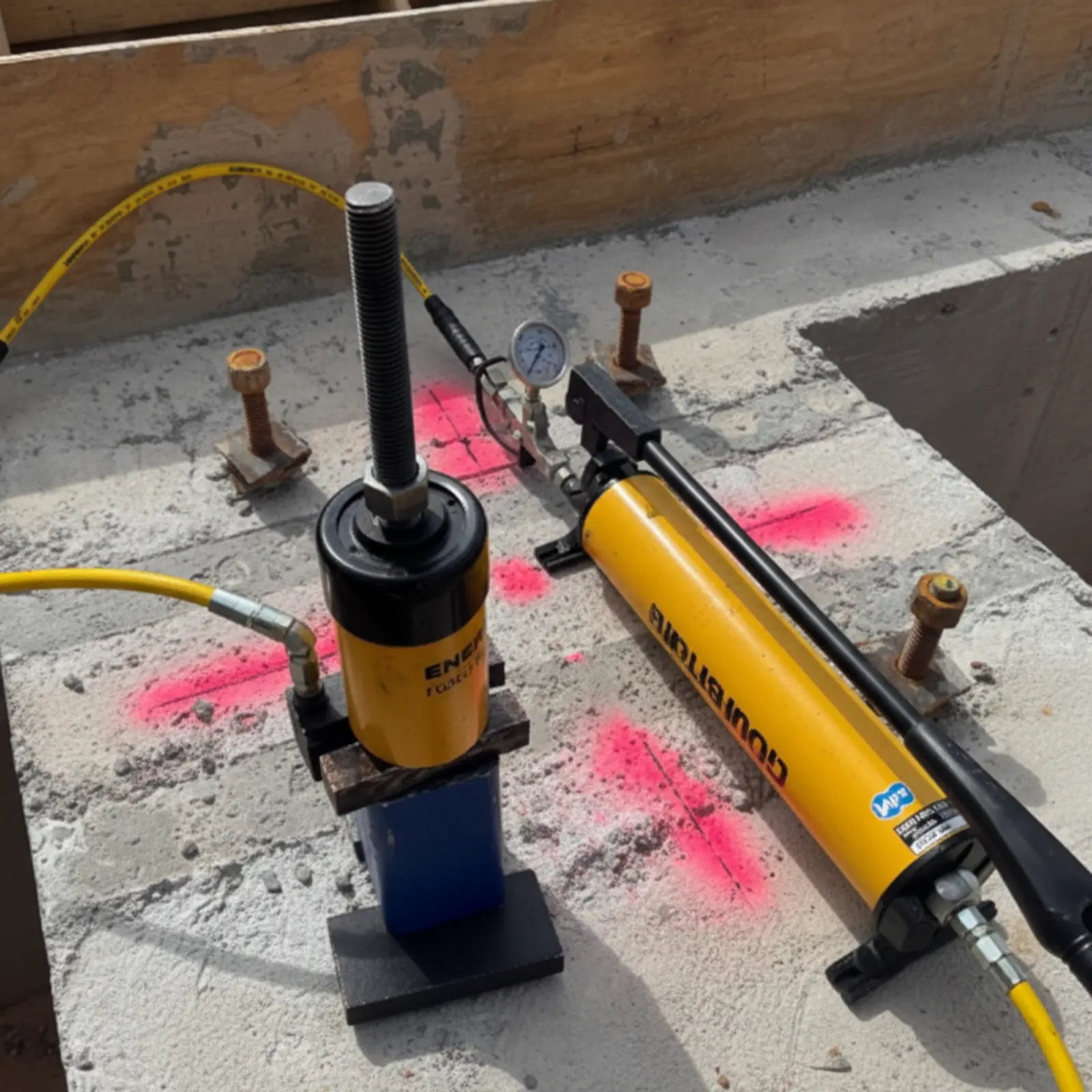
In unconfined anchor testing, the test rig supports are placed at least 1.5 times the effective embedment depth from the bolt center, allowing all failure modes — including concrete breakout — to develop naturally. In confined testing, supports are placed close to the anchor, compressing the surrounding concrete and preventing cone breakout. Unconfined testing is required when developing design values or when concrete breakout governs the design. Confined testing is acceptable only for proof load installation verification when the engineer confirms breakout does not control.
This distinction is critical because choosing the wrong test setup can mask installation failures, overstate anchor capacity, and produce results that do not reflect actual field conditions. Understanding when each is appropriate — and why — is one of the most common questions in anchor bolt pull testing.
How the Two Setups Differ
Unconfined Test Setup
Supports placed outside the projected breakout cone. All failure modes can develop. Required for design values and when breakout governs.
Confined Test Setup
Supports placed inside the cone. Compression prevents breakout. Tests bond/steel only. Acceptable for proof load verification when breakout doesn't govern.
The 1.5 × hef Support Distance Rule
For unconfined testing, the test rig supports must be placed at least 1.5 times the effective embedment depth from the bolt center. This dimension comes from the Concrete Capacity Design (CCD) method in ACI 318 Chapter 17, which defines the concrete breakout cone radius as 1.5 × hef. If the supports sit inside this radius, they compress the concrete above the failure cone and artificially prop up the anchor, producing a falsely high reading.
Worked Examples
3/4" bolt, 6" embedment
1.5 × 6" = 9" minimum from bolt center to each support
Bridge span = 18" minimum
1/2" bolt, 4" embedment
1.5 × 4" = 6" minimum from bolt center to each support
Bridge span = 12" minimum
1" bolt, 8" embedment
1.5 × 8" = 12" minimum from bolt center to each support
Bridge span = 24" minimum
Note: the bolt diameter does not affect this calculation. The breakout cone radiates from the bottom of the embedment at approximately 35 degrees regardless of bolt size. A 1/2" rod and a 1" rod embedded to the same depth produce the same cone geometry.
The European standard EOTA TR 048 is more conservative, requiring support reactions at least 2 × hef from the anchor. This is worth knowing when working with European-qualified anchors or on projects referencing EN 1992-4.
When Confined Testing Is Acceptable
Confined testing is allowed in three specific situations. First, for proof load testing to verify proper installation — not to develop design values. Second, for fully developed reinforcing bar connections in reinforced concrete where the surrounding reinforcement prevents cone breakout during service. Third, when the engineer of record specifically approves a confined setup for the application.
1. Proof Load Installation Verification
When you're checking that the installer cleaned the hole properly, used the correct adhesive, and allowed sufficient cure time, a confined proof load test is acceptable. The goal is pass/fail installation verification at a specified load — not capacity determination. ASTM E3121 is explicit: proof load tests performed in the confined condition shall not be used to develop design values.
2. Fully Developed Rebar Connections
When an adhesive anchor is a doweled rebar epoxied into a heavily reinforced member, cone breakout is not a realistic in-service failure mode because the surrounding reinforcement will intercept and redistribute the tension. Confined testing is generally sufficient for these installations.
3. Engineer of Record Approval
The EOR can specify confined testing when the application justifies it. The engineer must confirm — in the approved construction documents — that concrete breakout does not control the design tensile strength.
PTFE Sheet Requirement
For all confined tests, ASTM E3121 requires a PTFE (Teflon) sheet between the loading plate and the concrete surface, 0.020 ± 0.004 inches thick. The PTFE reduces friction so the plate's compressive reaction does not artificially boost the bond reading through friction effects.
When Unconfined Testing Is Required
Unconfined testing is required whenever the test results will be used to develop design values, when concrete breakout is the governing failure mode in the design, or when the engineer has not confirmed that breakout does not control. For adhesive anchors specifically, the code states: adhesive anchors shall be permitted to be tested in confined conditions only when the approved construction documents show that concrete breakout does not control the design tensile strength.
In practice, most field proof load testing of adhesive anchors should be unconfined. The most common installation errors — poor hole cleaning, insufficient adhesive, wet holes, inadequate cure time — all affect the bond. But incorrect embedment depth, which also causes failures, is easier to detect with an unconfined setup because a shallow anchor will break out under lower loads than expected.
The 0.75 Reduction Factor — Why Confined Tests Overstate Capacity
Research from the University of Wisconsin confirmed what practitioners have long observed: confined tests produce higher bond strength values than unconfined tests on identical anchors. ACI 355.4 applies a setup factor (αsetup) of 0.75 when converting confined test results to unconfined equivalents. This means confined tests can overstate actual in-service capacity by 25% or more.
The reason is mechanical. In a confined setup, the closely placed supports compress the concrete directly above where the breakout cone would form. This compression prevents the weakest failure mode (concrete breakout) from developing and forces the anchor to fail in bond or steel — both of which are typically stronger than breakout for a given embedment depth.
US vs. European Support Distance Standards
| Standard | Min. Support Distance | Region | Notes |
|---|---|---|---|
| ACI 318 / IBC | 1.5 × hef | United States | CCD method, breakout cone radius |
| EOTA TR 048 | 2.0 × hef | Europe | More conservative, used with EN 1992-4 |
For a 6-inch embedment, the US standard requires 9 inches minimum; the European standard requires 12 inches. On international projects or when using European-qualified anchors (ETA approvals), verify which standard governs the test setup.
Which Test Setup Do I Need?
Code References
ASTM E3121/E3121M-17
Section 1.1: Proof load tests performed in the confined condition to verify proper installation shall not be used to develop design values. Section 7: PTFE sheet requirements for confined testing (0.020 ± 0.004 in thickness).
ACI 318 Chapter 17
Defines the concrete breakout cone radius as 1.5 × hef using the Concrete Capacity Design (CCD) method. Breakout cone angle approximately 35 degrees from horizontal (1 vertical to 1.5 horizontal slope).
IBC 2024 Section 1705.3
Testing apparatus support locations shall not be within 1.5 times the anchor embedment depth. Exception: Adhesive anchors may be tested confined when approved construction documents show breakout does not control.
ACI 355.4-19
Qualification standard for post-installed adhesive anchors. Specifies the 0.75 setup reduction factor (αsetup) when converting confined bond strength results to unconfined equivalents.
EOTA TR 048 (2016)
European test procedure for post-installed fasteners in concrete. Requires support reactions at least 2 × hef from the anchor for unconfined tests — more conservative than the US standard.
Frequently Asked Questions
Need Anchor Pull Testing?
We perform both confined and unconfined anchor bolt pull testing across the Southeast — from Atlanta to Savannah, Macon, Chattanooga, Birmingham, and beyond. IBC 2024-compliant with calibrated Enerpac equipment and full documentation.
Request a Quote Call (404) 860-1288